Wiring diagram, howtos and diy wiki blog with HD images
Home
› Reading Wiring Diagrams - Wiring Diagrams Explained How To Read Wiring Diagrams Upmation - Literally, a circuit is the path that allows electricity to flow.
Reading Wiring Diagrams - Wiring Diagrams Explained How To Read Wiring Diagrams Upmation - Literally, a circuit is the path that allows electricity to flow.
Reading Wiring Diagrams - Wiring Diagrams Explained How To Read Wiring Diagrams Upmation - Literally, a circuit is the path that allows electricity to flow.. It is majorly used by building planners, architects, and electricians to present the wiring connections in a building, a room, or even a simple device. Knowing how to read circuits is a very useful skill that will help you out all the time. A digital multimeter is used to read voltage, current, resistance, continuity, and capacitance on the slightly higher priced meters. Www.handymanpf.complease help support this channel via paypal so i can continue to improve and make quality videos and make product reviews to help save you. Circuit or schematic diagrams consist of symbols representing physical components and lines representing wires or electrical.
Knowing how to cut, strip, and connect wire is an important electronics skill. We begin with a basics fuel pump & relay diagram Wiring diagram indicates that the wire does not apply to all vehicles, and is noted in the wiring diagram legend. A schematic can contain few or many symbols and connections and is normally read. Being able to master this competency will not only help you find solutions to common electrical problems a lot faster but will also give you a big headstart compared to less qualified technicians.
Wiring Diagrams Explained How To Read Wiring Diagrams Upmation from upmation.com Knowing how to cut, strip, and connect wire is an important electronics skill. To help illustrate the differences between wiring diagrams and schematics, a basic control circuit will first be explained as a schematic and then shown as a wiring diagram. Exactly like reading a book! Basics 10 480 v pump schematic : Basics 9 4.16 kv pump schematic : Getting from point a to point b. Basics 14 aov schematic (with block included) basics 15 wiring (or connection. Unlike a pictorial diagram, a wiring diagram uses abstract or simplified shapes and lines to show components.
Basics 13 valve limit switch legend :
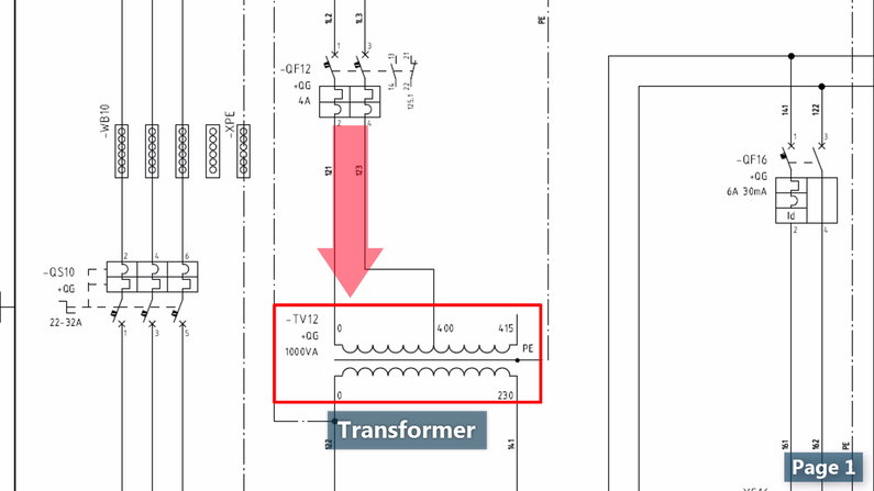
Wiring diagrams show how the wires are connected and where they should located in the actual device, as well as the physical connections between all the components. The power supply is shown at the top and the earth at the bottom to facilitate understanding of the current flow. To begin understanding how to read and. Basics 9 4.16 kv pump schematic : A first look at a circuit diagram may be confusing, but if you can read a subway map, you can read schematics. ¶ every motorcycle has a wiring system. A wiring diagram is used to represent how the circuit generally appears. A digital multimeter is used to read voltage, current, resistance, continuity, and capacitance on the slightly higher priced meters. Wiring diagrams explained how to read upmation how to read a schematic learn sparkfun com wiring diagrams explained upmation and understand an electrical schematics circuit basics subaru sambar diagram data have my advice in successful reading single line p id logic eep comprehensive guide edrawmax online petroed. Especially if you start messing around with building little electronics projects. A wiring diagram usually gives guidance more or less the relative point and harmony of devices and terminals upon the devices, to assist in building or servicing. Except for the ground and vcc symbols which just means connection to supply power. A beginner's guide to circuit diagrams.
This instructable will show you exactly how to read all those confusing circuit diagrams and then how to assemble the circuits on a breadboard! Learn to read electrical and electronic circuit diagrams or schematics. Www.handymanpf.complease help support this channel via paypal so i can continue to improve and make quality videos and make product reviews to help save you. Except for the ground and vcc symbols which just means connection to supply power. They can be accommodating when determining a fault in the connections, installing new wires and devices, locating electrical outlets, etc.
How To Read And Use Your Wiring Diagram Youtube from i.ytimg.com A wiring diagram is used to represent how the circuit generally appears. An electrical schematic is a diagram that shows how all of the wires and components in an electronic circuit are connected. Being able to master this competency will not only help you find solutions to common electrical problems a lot faster but will also give you a big headstart compared to less qualified technicians. A wiring diagram usually gives guidance more or less the relative point and harmony of devices and terminals upon the devices, to assist in building or servicing. And god saw the light, that it was good: Learning to read car wiring diagrams is a tremendous skill to add to your auto mechanic skillset. Basics 9 4.16 kv pump schematic : Basics 8 aov elementary & block diagram :
Reading schematics is just a matter of recognizing the symbols and see how they connect.
An electrical schematic is a diagram that shows how all of the wires and components in an electronic circuit are connected. Learn to read electrical and electronic circuit diagrams or schematics. We walk through some of the basics and most common symbols associated with reading an air conditioner wiring schematic or diagram. We begin with a basics fuel pump & relay diagram Literally, a circuit is the path that allows electricity to flow. To help illustrate the differences between wiring diagrams and schematics, a basic control circuit will first be explained as a schematic and then shown as a wiring diagram. Just try it, you will love it! Exactly like reading a book! To understand how to read ladder wiring diagrams, let's start with a simple electrical schematic consisting of a power supply, switch, and light, then you will move on to our control panel sample wiring diagrams. Basics 10 480 v pump schematic : If you know what to look for, it'll become second nature. To begin understanding how to read and. Basics 9 4.16 kv pump schematic :
Wiring diagrams were traditionally printed in book form, diagrams are big as you know, to fit them all on one page would make them unreadable. The purpose is the same: In part 1 of this series, you've learned how to read and understand a wiring diagram of an. And god said, let there be light: Especially if you start messing around with building little electronics projects.
Reading Hvac Electrical Wiring Diagrams For Troubleshooting Youtube from i.ytimg.com Learn to read electrical and electronic circuit diagrams or schematics. Oscilloscopes read and display the wave signal patterns going through the circuits, as well as the frequency, and other functions depending on the cost of the osciloscope. A schematic can contain few or many symbols and connections and is normally read. Breadboards are a great way to make temporary, functional, prototype circuits. Every one of them, bar none. To help illustrate the differences between wiring diagrams and schematics, a basic control circuit will first be explained as a schematic and then shown as a wiring diagram. A symbol usually represents a part. A drawing of an electrical or electronic circuit is known as a circuit diagram, but can also be called a schematic diagram, or just schematic.
Learn to read electrical and electronic circuit diagrams or schematics.
Every one of them, bar none. The lines between the symbols represents wires that connect. Literally, a circuit is the path that allows electricity to flow. Being able to master this competency will not only help you find solutions to common electrical problems a lot faster but will also give you a big headstart compared to less qualified technicians. Oscilloscopes read and display the wave signal patterns going through the circuits, as well as the frequency, and other functions depending on the cost of the osciloscope. A symbol usually represents a part. Learn to read electrical and electronic circuit diagrams or schematics. To understand how to read ladder wiring diagrams, let's start with a simple electrical schematic consisting of a power supply, switch, and light, then you will move on to our control panel sample wiring diagrams. They're like a map for building or troubleshooting circuits, and can tell you almost everything you need to know to understand how a circuit works. A well documented schematic outlines the functionality of an electric circuit and provides the basis for assembly and troubleshooting of a system. Angi matches you to local electricians who get the job done right. Reading schematics is just a matter of recognizing the symbols and see how they connect. A digital multimeter is used to read voltage, current, resistance, continuity, and capacitance on the slightly higher priced meters.